REVARQ ARC-6
Adaptive Energy.Reconfigured.
An adaptive photovoltaic array reconfiguration platform designed to sense module-level operating conditions and dynamically modify array topology.
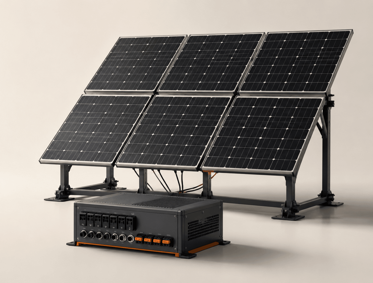
- REVARQ ARC-6
- Adaptive Photovoltaic Array Reconfiguration System
Engineered in India
Solar generation is dynamic.Its electrical architecture doesn’t have to be static.
Conventional photovoltaic arrays are typically interconnected in a fixed electrical configuration. Under non-uniform operating conditions, individual modules can experience different electrical behaviour.
ARC-6 investigates whether array topology itself can become an adaptive control variable.
The problem
One array.Different module conditions.
Six-module photovoltaic array under non-uniform operating conditions
Six photovoltaic modules are shown in one array, arranged three across and two deep. Five are under nominal conditions and one, PV5, is partially shaded across roughly the left half of its cells, illustrating non-uniform module operating conditions within a single array.
Causes of non-uniform operation
- Partial shadingshown
- Irradiance variation
- Temperature difference
- Soiling
- Orientation
- Module mismatch
Degradation and broader environmental variation contribute over longer timescales.
When module operating conditions diverge, their electrical characteristics can diverge as well.
In a fixed array architecture, those differences must still be accommodated within the existing interconnection.
Photovoltaic systems already manage these effects — bypass diodes limit the influence of a shaded cell string, and maximum power point tracking follows the operating point of an array or sub-array.
REVARQ is investigating a further control dimension: the electrical topology of the array itself. That is the problem space ARC-6 is built to examine.
Dynamic conditions
Every module experiences its own reality.
Module
Condition state
- PV1Nominal
- PV2Nominal
- PV3Irradiance variation
- PV4Nominal
- PV5Partial shading
- PV6Temperature variation
Illustrative condition states — not measured values
Operating conditions are not a property an array is commissioned with. They change through the day, across seasons, and with the environment a system happens to sit in.
A system that treats those conditions as fixed can only respond to them indirectly. One that measures them can respond to them deliberately.
REVARQ
- 01
Observes.
Module-level conditions are measured independently.
- 02
Evaluates.
Divergence between modules is assessed against the control strategy.
- 03
Adapts.
A permitted array topology is selected and applied.
If the operating condition can change, the system should be able to observe that change.
REVARQ ARC-6
Meet ARC-6.
Adaptive Photovoltaic Array Reconfiguration System
ARC-6 is REVARQ’s experimental platform for investigating module-level monitoring and controlled photovoltaic array reconfiguration.
It is a proof-of-concept engineering platform, built to make the idea testable in hardware rather than to demonstrate a finished product. What follows describes the prototype as it currently stands.
Current prototype
- PV modules
- 6
- Sensing
- Module-level
- Edge control
- ESP32
- Sensor bus
- I²C multiplexed
- Switching
- Relay matrix
- Operating modes
- AUTO / MANUAL
- Safe state
- SAFE/OFF
- Interface
- Web dashboard
Module-level sensing
ARC-6 observes every module,every moment.
Channels observed per module — no measured dataset is shown
The purpose is not simply to measure total array output.
The control system needs visibility into how individual modules are behaving before array-level decisions can be investigated. A single output reading describes the array; it does not describe the modules inside it.
The measurements taken at each module are electrical — voltage, current and the power derived from them. Irradiance, temperature and shading are inferred conditions, not quantities this sensing chain measures directly.
- Modules
- PV1 – PV6
- Sensing
- INA219, per module
- Bus
- TCA9548A I²C multiplexer
- Controller
- ESP32 edge controller
Six modules. Six independent perspectives. One adaptive array.
Control principle
Sense.Analyze.Decide.Reconfigure.Verify.
01
Sense
Observe module-level electrical behaviour.
Each module is measured independently rather than inferred from a single array reading.
02
Analyze
Evaluate individual module conditions and array behaviour.
Divergence between modules is what makes a topology decision worth considering at all.
03
Decide
Select an allowed array topology according to the control strategy.
The prototype's AUTO mode applies rule-based selection over the permitted topologies. It is not an autonomous optimiser, and it is not presented as one.
04
Reconfigure
Execute the permitted switching sequence.
The existing configuration is removed and the array passes through SAFE/OFF before another is established.
05
Verify
Measure the resulting electrical state.
Verification closes the loop: what it observes becomes the input to the next sensing cycle.
Verification is not the end of the process. The state it measures becomes the next observation, and the loop begins again.
Adaptive reconfiguration
What if the wiringcould respond?
ARC-6 investigates photovoltaic array topology as a controllable electrical variable.
The six modules remain physically unchanged. The permitted electrical interconnection can change.
- Displayed topology
- 6P
- Transition state
- SETTLED
6P established.
Select a configuration
Step 1 of 11
- 6P(settled)
- 6P(breaking)
- SAFE/OFF(safe)
- 2S3P(configuring)
- 2S3P(verifying)
- 2S3P(settled)
- 2S3P(breaking)
- SAFE/OFF(safe)
- 3S2P(configuring)
- 3S2P(verifying)
- 3S2P(settled)
Break-before-make
ARC-6’s reconfiguration sequence is designed around a disconnected intermediate state: the existing configuration is removed before another permitted configuration is established.
In the prototype control sequence there is no path from one operating topology directly to another. Every change passes through SAFE/OFF, where no operating conductors exist and the array output is isolated.
This is a controlled disconnected state within the ARC-6 architecture — a defined step in the switching sequence, not a fault condition and not a certified safety disconnect.
Supported topologies
One array.Multiple electrical configurations.
ARC-6 is designed to investigate controlled reconfiguration between a defined set of permitted photovoltaic array topologies.
The six physical modules remain the same. Their electrical interconnection changes.
Configuration
6P
Six modules in parallel.
- Modules in series
- 1
- Parallel strings
- 6
- Modules used
- 6
Strings
- PV1
- PV2
- PV3
- PV4
- PV5
- PV6
Six photovoltaic modules connected in parallel. Each module is connected between the positive and negative array buses.
System architecture
From module sensing to array output
In development — Phase 5
Hardware
Built to test the idea in hardware
In development — Phase 5 — awaiting prototype photography
Software
See what the array sees
In development — Phase 5
Controlled switching
Reconfiguration must be controlled
In development — Phase 4
Validation
We measure before we claim
In development — Phase 6 — awaiting experimental data
Applications
Where adaptive PV architecture could matter
In development — Phase 6
Roadmap
ARC-6 is the beginning
In development — Phase 6
About REVARQ
What if photovoltaic systems could adapt to the conditions they experience?
In development — Phase 7
How we build
Measure first. Adapt deliberately. Validate physically.
In development — Phase 7
Team
The engineers building REVARQ
In development — Phase 7 — awaiting team details
Mentors & advisors
Guided by experience
In development — Phase 7 — awaiting mentor details
Collaboration
Let's build what's next
In development — Phase 7 — awaiting contact address